Republic of Bashkortostan, Ufa, ul. Komsomolskaya, 15.
Russian version
Republic of Bashkortostan, Ufa, ul. Komsomolskaya, 15.
Russian version
Republic of Bashkortostan, Ufa, ul. Komsomolskaya, 15.
Russian version
Republic of Bashkortostan, Ufa, ul. Komsomolskaya, 15.
Russian version


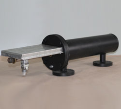
PTB-10Egeneral layout. PTB-10-64general layout.
GENERAL DATA
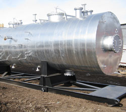
Modular tube furnace intended for heating of oil and oil emulsions during their infield transportation and treatment.
Liquid fuel furnace can be fabricated by individual order.
features
The main difference ofPTB-10E fromPTB-10-64 andPTB-10Aimpliesin usage of electric actuators on gas hookup and utilization of six-row coil is used instead of the 4-row one.
Climatic modification – U, HL by GOST 15150-69.
Placement category–1 by GOST15150-69.
Common specifications
|
Parameter |
Value |
|||
|
PTB-10А |
PTB-10E |
PTB-10-64 |
PTB-10Zh |
|
|
Rated heat capacity, MW |
5.5…11.6 |
5.5…13.9 |
5.5…11.6 |
5.5…13.9 |
|
Heated product related productivity, t/hr, within |
200…416.6 |
200…500 |
200…416.6 |
200…500 |
|
Product temperature, °С: - at furnace input, min - at furnace output, max |
+5 +90 |
|||
|
Efficiency factor, % , max |
80 |
|||
|
Product coil pressure, MPa (kgf/cm2): - working, max; - estimated; - hydro tested. |
6.3 (63) 6.3 (63) 8.2 (82) |
|||
|
Fuel gas parameters (natural/associated oil gas) - hydrogensulphide content (H2S), % mass. max; - furnace input pressure, MPa (kgf/m2), within; - pressure before combustion chamber, MPa, within; - air pressure inside combustion chamber, kPa; - gas pressure before primer burner, MPa, within; - primer burner fuel gas consumption, nm3/hr (nm3/sec); - fuel gas consumption, nm3/hr; - air consumption, nm3/hr. |
0.002 0.1…0.3 (1.0…3.0) 0.005…0.05
3.0 0.06…0.18
3.0 (0.00085)
1600 24000 |
- |
||
|
Fuel parameters (diesel fuel, oil): - lower combustion heat, kcal/kg - hydrogen sulphide content (H2S), mass fraction, % max - pressure before nozzle, MPa (kgf/cm2), max - fuel consumption, kg/hr |
- |
6800
0.002 4.0 (40.0) 1600 |
||
|
Number of combustion chambers |
4 |
|||
|
Mass, kg, max: - furnace (in idle state); - heat exchange chamber; - furnace foundation block; - ventilation set block. |
40000 28500 7700 1500 |
46950 32500 7700 1500 |
40000 28500 7700 1500 |
46950 32500 7700 1500 |
|
Servicelife, years, min |
10 |
|||
|
Averageoverhaullife, years |
3.5 |
|||

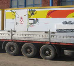
1) furnace foundation block;
2) heat exchange chamber;
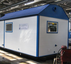
3) ventilator set block;
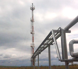
4) fume stack;
5) explosive valve
PTB-10Аgeneral drawing.
|
Chokes and Flanges Table |
||||
|
Ref |
Designation |
Qty |
Nominal |
DN, mm |
|
A1 |
Product inlet |
1 |
6.3 (63) |
300 |
|
Б1 |
Product outlet |
1 |
6.3 (63) |
300 |
|
В1 |
Fuel gas inlet |
1 |
0.6 (6) |
80 |
|
Г1 |
Gas outlet to candle |
1 |
- |
50 |
|
Д1 |
Oil line steam inlet |
2 |
6.3 (63) |
100 |
|
Е1 |
Heat exchange chamber steam inlet |
1 |
- |
100 |
|
Ж1 |
Heat exchange chamber drainage |
2 |
- |
50 |
|
З1 |
Observation window |
1 |
- |
80 |
|
И1 |
Temperature adjustment bottle |
1 |
- |
50 |
|
К1 |
Heat exchange chamber air medium sampling |
1 |
- |
50 |
|
Л1 |
Fume gas temperature control |
4 |
- |
20 |

1)heat exchange chamber;
2)furnace foundation block;
3)ventilator set block;
4)explosive valve block
5)fume stack
PTB-10E general drawing.
|
Chokes and Flanges Table |
||||
|
Ref |
Designation |
Qty |
Nominal |
DN, mm |
|
A1 |
Oil inlet |
1 |
6.3 (63) |
300 |
|
Б1 |
Oil outlet |
1 |
6.3 (63) |
300 |
|
В1 |
Fuel inlet from GRP |
1 |
1.6 (16) |
50 |
|
Г1, 2 |
Firefighting chokes |
2 |
0.6 (6) |
100 |
|
Д1, 2 |
Drainage |
2 |
0.1 (1) |
25 |
|
Е1 |
Condensate discharge |
1 |
0.6 (6) |
25 |
|
Ж1 |
Pressure sampling |
1 |
0.1 (1) |
15 |
|
И1, 2 |
Observation window |
2 |
- |
100 |
|
К1, 2 |
Air vent plug |
2 |
6.3 (63) |
15 |
|
Л1-4 |
Fume gas outlet |
4 |
200x1500 |
|
|
М1 |
Candle |
1 |
0.6 (6) |
25 |
|
Н1 |
Heat exchange chamber air-gas medium control |
1 |
- |
50 |
|
У1, 2 |
Fume gas temperature control |
2 |
- |
15 |

2 – Furnace foundation block
3 – Ventilation set block
4 – Explosive valve block
5 – Fume stack
6 – Oil input line
7 – Oil output line
8 – Service board
9 – Ladder
10 – Gas heating coil piping
PTB-10-64 general drawing.
|
Chokes and Flanges Table |
||||
|
Ref |
Designation |
Qty |
Nominal |
DN, mm |
|
A1 |
Oil inlet |
1 |
1.6 (16) |
300 |
|
Б1 |
Oil outlet |
1 |
1.6 (16) |
300 |
|
В1 |
Fuel gas inlet |
1 |
0.6 (6) |
80 |
|
Г1 |
Firefighting inlet |
2 |
6.3 (63) |
100 |
|
Д1 |
Drainage |
2 |
- |
50 |
|
Е1 |
Condensate discharge |
1 |
- |
25 |
|
Ж1 |
Pressure sampling |
1 |
0.1 (1) |
50 |
|
З1 |
Observation window |
1 |
- |
80 |
|
И1 |
Fume gas temperature control |
2 |
- |
M20x1.5 |
|
К1 |
Flaring output |
1 |
- |
25 |