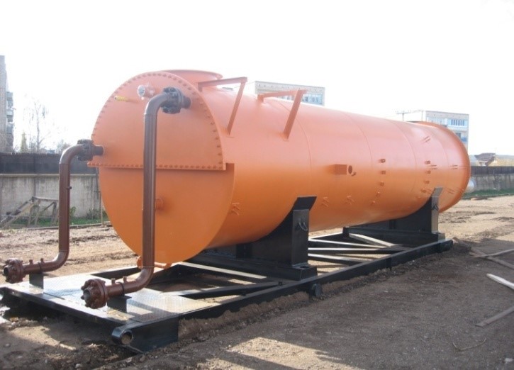
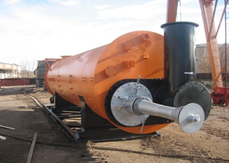
PNPT-0.63general layout.
GENERALDATA
Capacitance type intermediate heat carrier line heater PNPT intended for heating oil and oil products during transportation, as well as oil emulsions at oil treatment units.
features
Climatic modification – U, HL by GOST 15150-69.
Placement category – 1 by GOST15150-69.
Common specifications
|
Parameter |
Value |
||
|
PNPT-0.63 |
PNPT-1.6 |
PNPT-3.87 |
|
|
Rated heat capacity, MW (Gcal/hr) |
0.73 (0.63) |
1.86 (1.6) |
4.5 (3.87) |
|
Heated product related productivity, t/day, (kg/sec): |
1150 |
1650 |
2000…10000) |
|
Product temperature, °С: |
+5 |
||
|
Efficiency factor, % , max |
80 |
85 |
|
|
Intermediate heat carrier |
Sweet water, ethylene glycol solution, other inflammable heat carriers |
||
|
Product coil pressure, MPa (kgf/cm2): |
6.3 (6.3) |
||
|
Heated medium parameters: |
oil, oil emulsion, formation water |
||
|
Fuel parameters (natural or associated oil gas): - pressure before burner, MPa (kgf/cm2), - hydrogen sulphide content, % mol., max |
8365…14340 |
8365…14340 |
|
|
- fuel gas consumption, m3/hr, |
≤100 |
≤215 |
60…593 |
|
Mass without intermediate heat carrier, kg, max: |
13000 |
19100 |
43000 |
|
Service life, years, min |
10 |
||
|
Reliability parameters: |
3.5 |
||
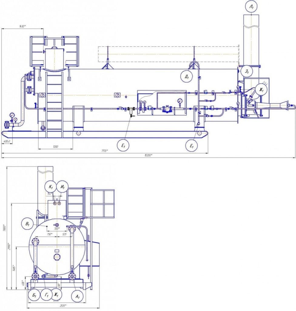 PNPT-0.63 general drawing.
PNPT-0.63 basic assembly units:
|
Chokes and Flanges Table |
||||
|
Ref |
Designation |
Qty |
Nominal |
DN, mm |
|
A1 |
Oil inlet |
1 |
6.3 (63) |
100 |
|
Б1 |
Oil outlet |
1 |
6.3 (63) |
100 |
|
В1 |
Fuel gas inlet |
1 |
1 .6 (16) |
25 |
|
Г1 |
Tank drainage |
1 |
1 .6 (16) |
50 |
|
Д1 |
Fuel gas purge to candle |
1 |
1 .6 (16) |
25 |
|
Е1 |
Drainage of fuel gas lines |
2 |
1 .6 (16) |
25 |
|
Ж1 |
Assembly choke |
3 |
0.1 (1.0) |
100 |
|
З1 |
Observation choke |
1 |
0.1 (1.0) |
80 |
|
И1 |
Heat carrier supply |
1 |
1 (10) |
20 |
|
К1 |
Heat carrier drainage |
1 |
1 (10) |
20 |
|
Л1 |
Fume gas outlet |
1 |
0.1 (1.0) |
500 |
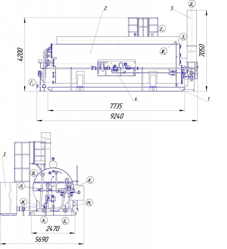 PNPT-1.6 basic assembly units:
PNPT-1.6 general drawing.
|
Chokes and Flanges Table |
||||
|
Ref |
Designation |
Qty |
Nominal |
DN, mm |
|
A1 |
Heated product inlet |
1 |
6.3 (63) |
100 |
|
Б1 |
Heated product outlet |
1 |
6.3 (63) |
100 |
|
В1 |
Fuel gas inlet |
1 |
1.0 (10) |
50 |
|
Г1 |
Heat carrier drainage |
1 |
0.1 (1.0) |
50 |
|
Д1 |
Fume gas outlet |
1 |
0.1 (1.0) |
500 |
|
Е1 |
Intermediate heat carrier inlet |
1 |
0.1 (1.0) |
100 |
|
Ж1 |
Fuel gas purge to candle |
1 |
0.1 (1.0) |
25 |
|
З1 |
Observation window |
2 |
- |
80 |
|
И1 |
Heated product inlet line pressure control |
3 |
6.3 (63) |
(M20x1.5) |
|
К1 |
Heated product outlet line pressure control |
2 |
6.3 (63) |
(M20x1.5) |
|
Л1 |
Heated product inlet line temperature control |
2 |
6.3 (63) |
(M20x1.5) |
|
М1 |
Heated product outlet line temperature control |
2 |
6.3 (63) |
(M20x1.5) |
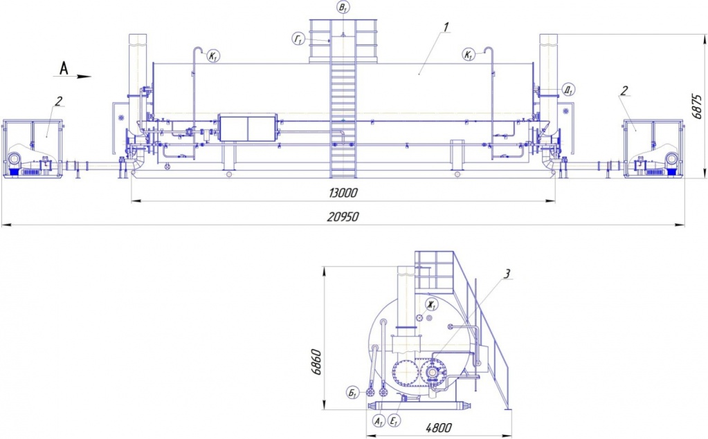 PNPT-3.87 basic assembly units:
PNPT-3.87 general drawing.
|
Chokes and Flanges Table |
||||
|
Ref |
Designation |
Qty |
Nominal |
DN, mm |
|
A1 |
Heated product inlet |
2 |
6.3 (63) |
100 |
|
Б1 |
Heated product outlet |
2 |
6.3 (63) |
100 |
|
В1 |
Heat carrier loading |
1 |
- |
100 |
|
Г1 |
Heat carrier overflow |
1 |
- |
15 |
|
Д1 |
Gas supply |
1 |
- |
50 |
|
Е1 |
Drainage |
1 |
- |
50 |
|
Ж1 |
Coil hatch |
2 |
- |
150 |
|
К1 |
Purge |
2 |
- |
20 |