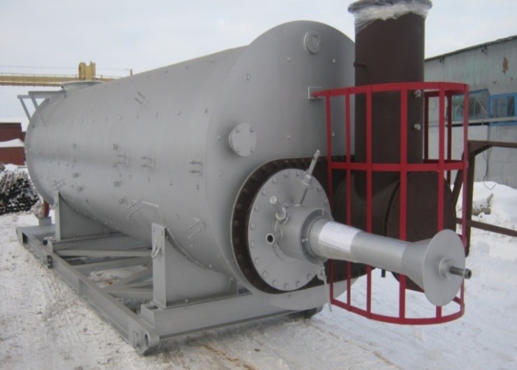
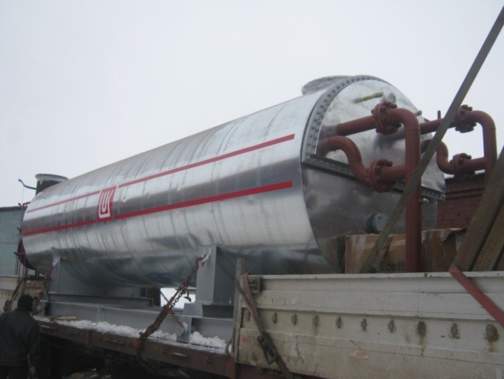
PP-0.63A general layout.
GENERAL DATA
Heaters intended for heating of oil products as well as oil emulsions at transporting and oil treating facilities.
features
Climatic modification – U, HLby GOST 15150-69.
Placement category–1 by GOST15150-69.
Common specifications
|
Parameter |
Value |
|||
|
PP-0.63А |
PP-0.63АZh |
PP-0.63AMZhG |
PP-0.63AS |
|
|
Rated heat capacity, MW (Gcal/hr) |
0.73 (0.63) |
|||
|
Heated product related productivity, t/day: - oil emulsion, water content 30% mass, at t =25°С |
1150 |
|||
|
Product temperature, °С: - at heater input, min - product output - intermediate carrier heating |
+5 +70 +95 |
|||
|
Efficiency factor, %, max |
80 |
|||
|
Intermediate heat carrier |
Sweet water, ethylene glycol solution, other inflammable heat carriers |
|||
|
Product coil pressure, MPa (kgf/cm2) : - working, max - estimated - hydro tested |
6.3 (63) 6.3 (63) 8.2 (82) |
|||
|
Heated medium parameters: - title - density at 20°С, kg/m3, max - viscosity at 20°С, cSt - hydrogen sulphide content (H2S), % mol., max - carbon dioxide content (СО2), % mol., max |
oil, oilemulsion 900 100 0.01 1.0 |
|||
|
Fuel parameters (natural or associated oil gas): - hydrogen sulphide content (H2S) , mass fraction, % max - combustion heat, MJ/m3, within - pressure at fuel treating unit input, MPa (kgf/cm2) within - pressure before burner, MPa (kgf/cm2) within
- fuel gas consumption, m3/hr, max |
0.002 35…60 0.2…0.4 (2.0…4.0) 0.07…0.15 (0.7…1.5) 100 |
- |
0.002 35…60 0.2…0.4 (2.0…4.0) 0.03 (0.3) 100 |
5 35…60 0.2…0.4 (2.0…4.0) 0.07…0.15 (0.7…1.5) 100 |
|
Fuel parameters (diesel fuel or oil): - lower combustion heat, kcal/kg - hydrogen sulphide content (H2S), mass fraction, % max - pressure before nozzle, MPa (kgf/cm2), max - fuel oil consumption, kg/hr, within |
- |
6800
0.002 4.0(40.0) 50…100 |
- |
|
|
Mass, kg, max: - without intermediate heat carrier. |
13000 |
13000 |
13880 |
13000 |
|
Service life, years, min |
10 |
|||
|
Reliability parameters: - average trouble-free life, years, min |
3.5 |
|||
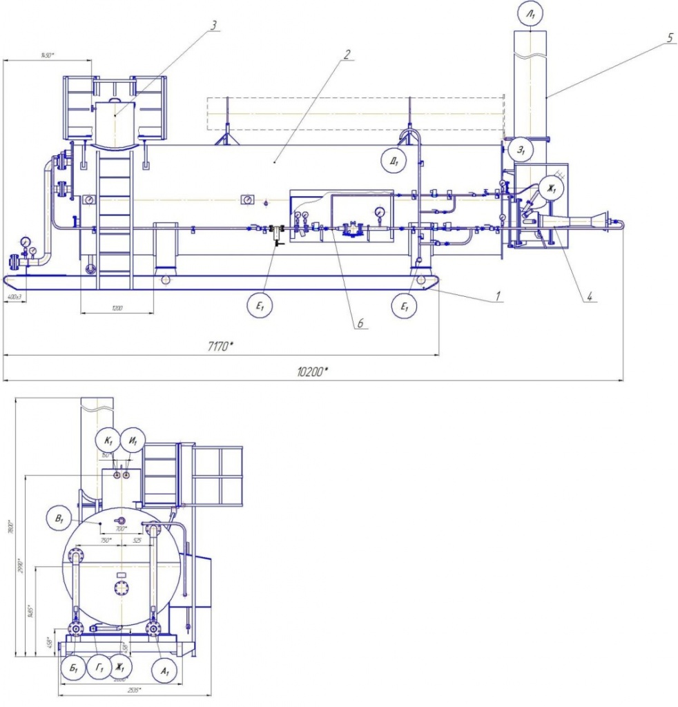
PP-0.63A basic assembly units:
1) skid frame;
2) furnace shell;
3) expansion tank;
4) burner device;
5) fume stack;
6) fuel treating block
|
Chokes and Flanges Table |
||||
|
Ref |
Designation |
Qty |
Nominal |
DN, mm |
|
A1 |
Oil inlet |
1 |
6.3 (63) |
100 |
|
Б1 |
Oil outlet |
1 |
6.3 (63) |
100 |
|
В1 |
Fuel gas inlet |
1 |
1.6 (16) |
25 |
|
Г1 |
Tank drainage |
1 |
1.6 (16) |
50 |
|
Д1 |
Fuel gas purge to candle |
1 |
1.6 (16) |
25 |
|
Е1 |
Drainage of fuel gas lines |
2 |
1.6 (16) |
25 |
|
Ж1 |
Assembly choke |
3 |
0.1 (1.0) |
100 |
|
З1 |
Observation choke |
1 |
0.1 (1.0) |
80 |
|
И1 |
Heat carrier supply |
1 |
1 (10) |
20 |
|
К1 |
Heat carrier excess discharge |
1 |
1 (10) |
20 |
|
Л1 |
Fume gas outlet |
1 |
0.1 (1.0) |
500 |
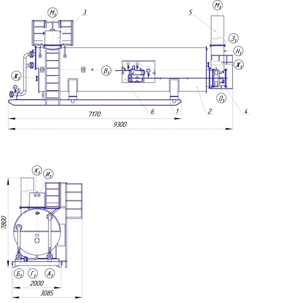
1) skid frame;
2) furnace shell;
3) expansion tank;
4) burner device;
5) fume stack;
6) fuel treating block
PP-0.63АZh general drawing.
|
Chokes and Flanges Table |
||||
|
Ref |
Designation |
Qty |
Nominal |
DN, mm |
|
A1 |
Oil inlet |
1 |
6.3 (63) |
100 |
|
Б1 |
Oil outlet |
1 |
6.3 (63) |
100 |
|
В1 |
Fuel gas inlet |
1 |
1.6 (16) |
25 |
|
Г1 |
Tank drainage |
1 |
1.6 (16) |
50 |
|
Ж1 |
Assembly choke |
1 |
0.1 (1.0) |
100 |
|
З1 |
Observation choke |
1 |
0.1 (1.0) |
80 |
|
Н1 |
Heat carrier supply |
1 |
1 (10) |
20 |
|
К1 |
Heat carrier discharge |
1 |
1 (10) |
20 |
|
М1 |
Fume gas outlet |
1 |
0.1 (1.0) |
500 |
|
Н1 |
Sampling choke with gas analyzer |
1 |
0.1 (1.0) |
20 |
|
О1 |
Drainage of furnace condensate |
1 |
0.1 (1.0) |
15 |
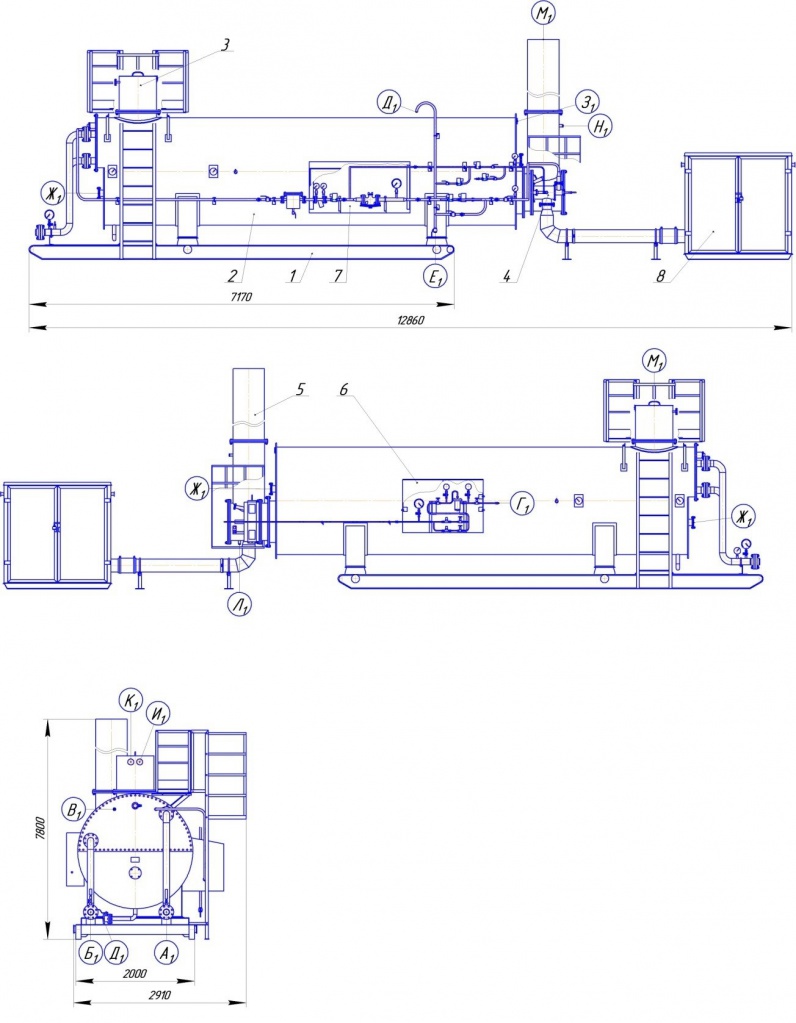
PP-0.63AMZhG basic assembly units:
1) skid frame;
2) furnace shell;
3) expansion tank;
4) burner device;
5) fume stack;
6) liquid fuel treating cabinet;
7) gaseous fuel treating cabinet;
8) ventilation set block
PP-0.63AMZHG general drawing.
|
Chokes and Flanges Table |
||||
|
Ref |
Designation |
Qty |
Nominal |
DN, mm |
|
A1 |
Oil inlet |
1 |
6.3 (63) |
100 |
|
Б1 |
Oil outlet |
1 |
6.3 (63) |
100 |
|
В1 |
Fuel gas inlet |
1 |
1.6 (16) |
25 |
|
Г1 |
Liquid fuel inlet |
1 |
4.0 (40) |
10 |
|
Д1 |
Tank drainage |
1 |
1.6 (16) |
50 |
|
Ж1 |
Assembly choke |
1 |
0.1 (1.0) |
100 |
|
З1 |
Observation choke |
1 |
0.1 (1.0) |
80 |
|
И1 |
Heat carrier supply |
1 |
1 (10) |
20 |
|
К1 |
Heat carrier discharge |
1 |
1 (10) |
20 |
|
Л1 |
Drainage of furnace condensate |
1 |
0.1 (1.0) |
15 |
|
М1 |
Fume gas outlet |
1 |
0.1 (1.0) |
500 |
|
Н1 |
Sampling choke with gas analyzer |
1 |
0.1 (1.0) |
20 |
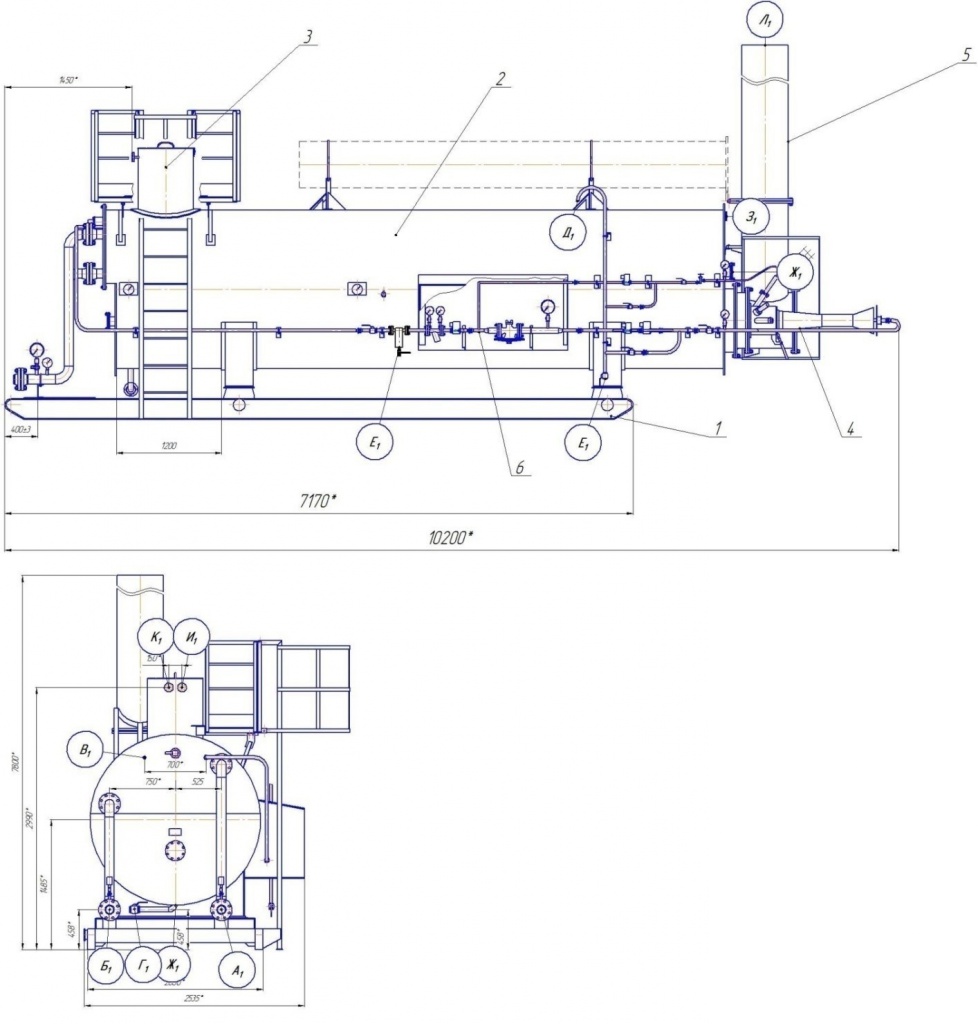
1) skid frame;
2) furnace shell;
3) expansion tank;
4) burner device;
5) fume stack;
6) fuel treating block
PP-0.63AS general drawing.
|
Chokes and Flanges Table |
||||
|
Ref |
Designation |
Qty |
Nominal |
DN, mm |
|
A1 |
Oil inlet |
1 |
6.3 (63) |
100 |
|
Б1 |
Oil outlet |
1 |
6.3 (63) |
100 |
|
В1 |
Fuel gas inlet |
1 |
1.6 (16) |
25 |
|
Г1 |
Tank drainage |
1 |
1.6 (16) |
50 |
|
Д1 |
Fuel gas purge to candle |
1 |
1.6 (16) |
25 |
|
Е1 |
Drainage of fuel gas lines |
2 |
1.6 (16) |
25 |
|
Ж1 |
Assembly choke |
3 |
0.1 (1.0) |
100 |
|
З1 |
Observation choke |
1 |
0.1 (1.0) |
80 |
|
И1 |
Heat carrier supply |
1 |
1 (10) |
20 |
|
К1 |
Heat carrier excess discharge |
1 |
1 (10) |
20 |
|
Л1 |
Fume gas outlet |
1 |
0.1 (1.0) |
500 |