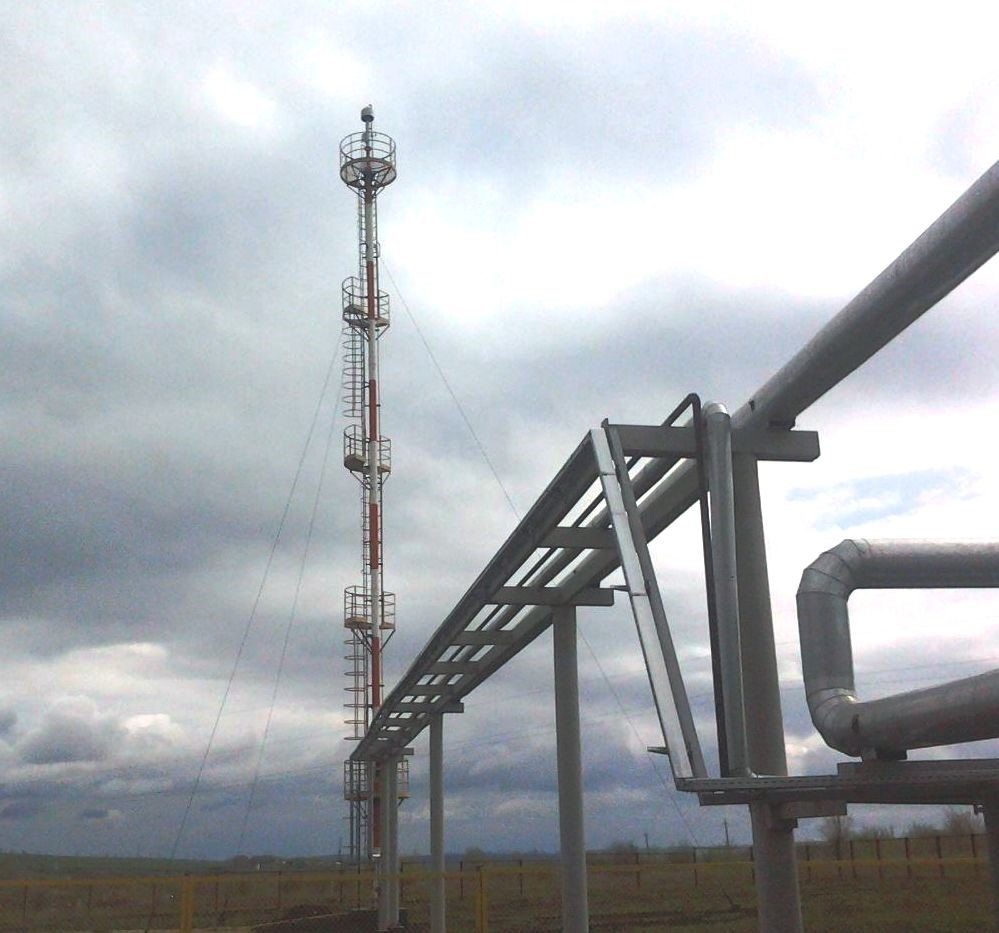
GENERAL DATA
The unit intended for high-efficient gas combustion during emergency, periodical and constant release at oil, water, gas treating facilities of oil and gas fields.
EQUIPMENT MODIFICATION
Operating conditions should correspond to U, HL by GOST 15150-69.
Placement category – 1by GOST15150-69.
|
Designation |
Tip diameter, mm (D) |
Flaring gas volume, 1000 m3/day |
Stack height, m (H) |
Stack diameter, mm (D1) |
Recommended number of pilot burners |
|
UFMS-50 |
50 |
21 |
5 |
100.150 |
1 |
|
UFMS-100 |
100 |
61 |
7 |
100.150 |
1 |
|
UFMS-150 |
150 |
146 |
10 |
150,200 |
1 |
|
UFMS-200 |
200 |
256 |
14 |
200,300,400 |
1 |
|
UFMS-250 |
250 |
402 |
17 |
250 |
2 |
|
UFMS-300 |
300 |
585 |
21 |
300 |
2 |
|
UFMS-350 |
350 |
792 |
24 |
350 |
2 |
|
UFMS-400 |
400 |
975 |
27 |
400 |
2 |
|
UFMS-500 |
500 |
1460 |
34 |
500 |
2 |
|
UFMS-600 |
600 |
2130 |
40 |
600 |
3 |
|
UFMS-750 |
750 |
3290 |
49 |
750 |
3 |
|
UFMS-900 |
900 |
4750 |
61 |
900 |
3 |

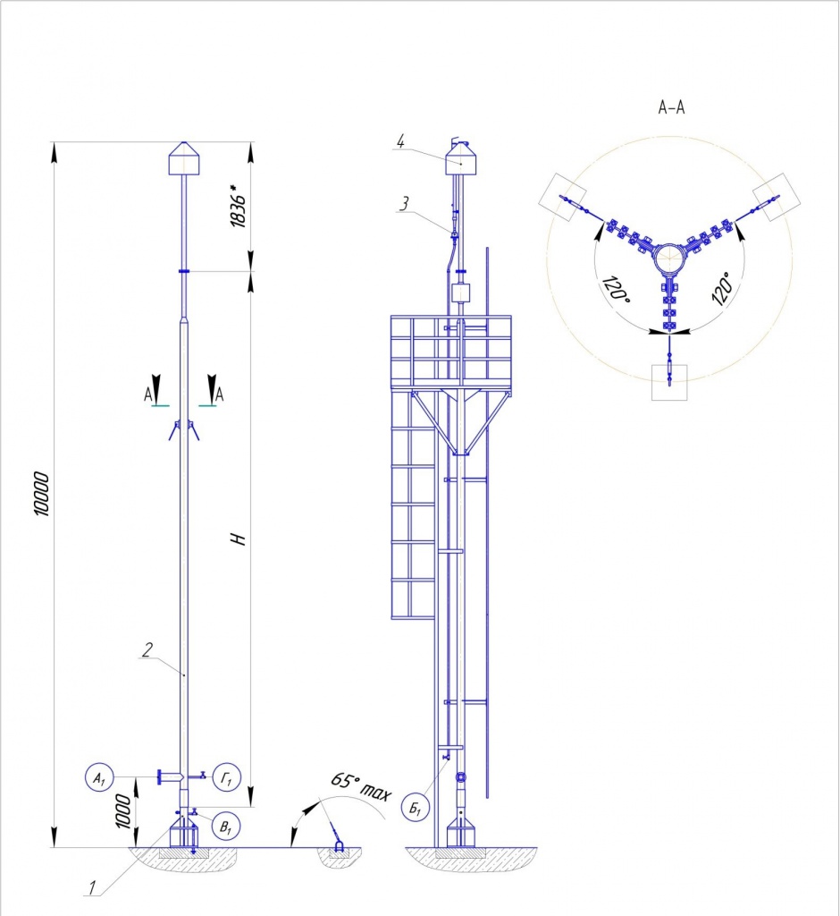
1) foundation;
2) stack;
3) pilot burner;
4) spray tip
|
Chokes and Flanges Table |
||||
|
Ref |
Designation |
Qty |
Nominal |
DN, mm |
|
A1 |
Oil & gas mixture inlet |
1 |
0.6 (6.0) |
100 |
|
Б1 |
Oil outlet |
1 |
0.07 (0.7) |
25 |
|
В1 |
Water outlet |
1 |
0.6 (6.0) |
15 |
|
Г1 |
Fuel gas inlet |
1 |
0.6 (6.0) |
25 |
Singletip UFMS general drawing.

|
Chokes and Flanges Table |
||||
|
Ref |
Designation |
Qty |
Nominal |
DN, mm |
|
A1 |
Oil & gas mixture inlet |
1 |
0.6 (6.0) |
200 |
|
Б1 |
Oil outlet |
1 |
0.6 (6.0) |
200 |
|
В1,2 |
Water outlet |
2 |
0.6 (6.0) |
25 |
|
Г1,2,3 |
Fuel gas inlet |
2 |
0.07 (0.7) |
25 |
|
Д1,2 |
Gas condensate drainage |
2 |
0.6 (6.0) |
15 |
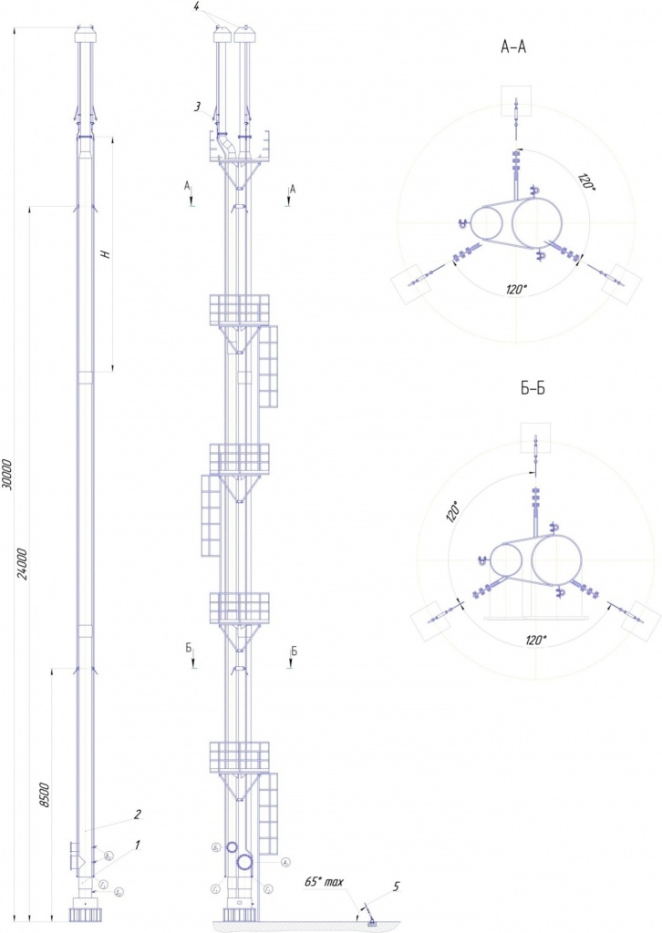
UFMS
basic assembly units:
1) foundation;
2) stack;
3) pilot burner;
4) spray tip;
5) rope
Double tip UFMS general drawing.