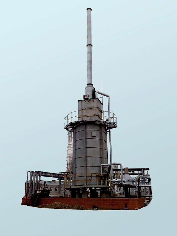
The furnace designed for heating and partial evaporation of diesel fraction coming from column cubeТ-401, with subsequent return into T-401 column as a “hot stream”.
features
Operation conditions should correspond to U, HL by GOST 15150-69.
Placement category –1 by GOST15150-69.
Maximal block installation area seismic activity – 6 points by SNiP 11-7-81.
The furnace has 2 coils:
1) Coil №1 works with diesel fraction;
2) Coil №2 works with fuel gas.
COMMON SPECIFICATIONS
Common specifications presented in tables below.
Coil 1 specification list.
|
Parameter |
Value |
|
Nominal heat release, MW |
1.056 |
|
Diesel fraction related productivity, kg/hr |
22285 |
|
Temperature, °С: - at furnace input, within; - at furnace output, max; - wall temperature, designed; - coil walls, min allowable |
+304 +328 +440 minus 47 |
|
Coil pressure, MPa (kgf/cm2): - process; - working, max; - designed; - hydro tested. |
0.5…0.6 (5.0…6.0) 0.77 (7.7) 0.8 (8.0) 1.47 (14.7) |
|
Heated medium parameters: - title; - hazard class; - explosion risk; - fire risk; - explosion hazard zone class. |
diesel fraction 4 by GOST 12.1.007-76 yes yes 2 by GOST Р 51330.9-99 |
|
Corrosion allowance, mm |
2 |
|
Radiant tube heating surface area, m2 |
40.6 |
|
Service life, years, min: - coil; - furnace. |
10 15 |
|
Furnace mass, kg max: - in idle state; - during hydro test. |
23000 25130 |
Coil 2 specification list.
|
Parameter |
Value |
|
Nominal heat release, MW |
1.056 |
|
Fuel gas related productivity, m3/hr |
61±15% |
|
Temperature, °С: - at furnace input, within; - wall temperature, designed; - coil walls, min allowable |
+40…+50 +70 minus 47 |
|
Coil pressure, MPa (kgf/cm2) : - process |
0.01…0.1 (0.1…1.0) |
|
Heated medium parameters - title; - hazard class; - explosion risk; - fire risk; - explosion hazard zone class. |
fuel gas 4 by GOST 12.1.007-76 yes yes 2 by GOST Р 51330.9-99 |
|
Corrosion allowance, mm |
2 |
|
Service life, years, min: - coil; - furnace. |
10 15 |
|
Furnace mass, kg max: - in idle state; - during hydro test. |
23000 25130 |

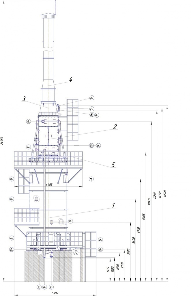
N-402 basic assembly units:
1) radiant section;
2) convection section;
3) regulating gate;
4) fume stack;
5) platform.
N-402 general drawing.
|
Chokes and Flanges Table |
||||
|
Ref |
Designation |
Qty |
Nominal Pressure, MPa (kgf/cm2) |
DN, mm |
|
A1 |
Product inlet |
1 |
1.6 (16) |
100 |
|
Б1 |
Product outlet |
1 |
150 |
|
|
В1 |
Drainage |
1 |
80 |
|
|
Г1 |
Burner fuel gas inlet |
1 |
32 |
|
|
Д1 |
Primer installation choke |
1 |
15 |
|
|
Е1 |
Gas or nitrogen input |
1 |
80 |
|
|
Ж1, 2, 3 |
Underpressure measurement |
3 |
- |
15 (M20x1.5)
|
|
И1,2 |
Heat converter installation choke |
2 |
||
|
К1 |
Fume gas analyzer installation choke |
1 |
|
M16 |
|
Л1 |
Photosensor installation choke |
1 |
|
80 |
|
М1, 2 |
Exhaust window |
2 |
|
500 |
|
Н1 |
Inspection hole |
3 |
|
150x220 |
|
О1 |
Bottom inspection hole |
1 |
|
100 |
|
П1 |
Manhole hatch |
1 |
|
450x540 |
|
Р1 |
Observation hole |
1 |
|
400 |
|
С1 |
Sanitation hole |
1 |
|
200 |